 |
| m500 cradle: USB to RS-232
. |
| The Palm m500 series is coming with the USB version of the cradle only.
If you need an RS-232 cradle, you had to buy it extra. But both versions
are using the same little printed curcuit board to hold the universal connector.
On this PCB you can find both cable layouts, the USB and the RS-232 cable.
So adding a simple RS-232 cable and changing one resistor is all it takes.
If you add a switch, you can even build a dual-version. There are ways
to switch electronically between USB and RS-232, but IMHO they all have
disadvantages. If you use the serial DTR signal to switch to the serial
ID, you have to make sure the RS-232 port is not open if you want to use
USB. That means fiddling with the hotsync manager which services basically
both conection types. And you'd need additional electronics. You can also
build a kind of 'cable-ID', but then you can't keep both cables connected
at the same time. I found a switch is the most convenient way.
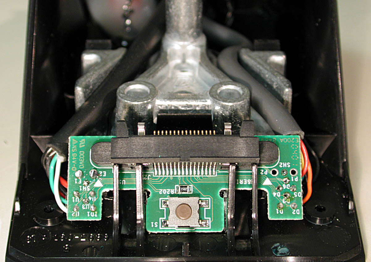
. First you need a Torx screwdriver, size 6, to open the 4 screws that hold the cradle together. The screws are hidden under the 4 little rubber feet. If you remove the feet, do it carefully and try to keep the adhesive tape on the rubber, then you can re-use it later. Once the screws are gone, the cradle is basically falling apart. Just watch the hotsync button, it's the only loose part. Now you can see the PCB with the USB cable attached left side of the connector, the image below is showing it (you can magnify all images on this page by clicking on them). . |
|
|
|
|
| .
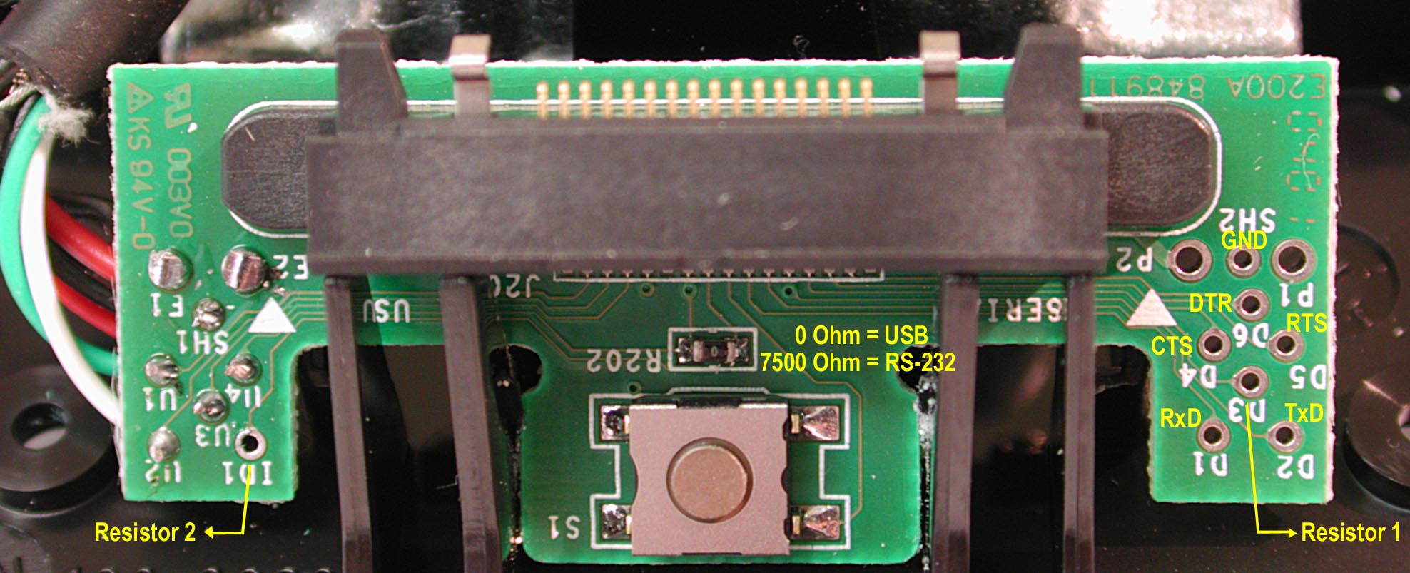
As long as you don't have an original Palm serial cable with power supply lines like it's used in the Palm IIIc cradle, I would recommend to keep the USB cable even if you want a serial version only. If you remove it totally, you'll loose the connection to the power supply. The original serial cable of the IIIc has two additional power lines and the right DC-connector worked into the 9-pin SUB-D plug, but I wouldn't know where to get such a cable (unless you rip it out of a IIIc cradle). . On the table below you can see the necessary signals and where they belong to. On the right right side of the PCB you'll find solder points named D1 - D6 and P1 and SH2 which are already connected to the right serial pins of the connector. All you need now, is a 6 line cable (or 5 lines + shield) that connects these solder points to a 9-pin SUB-D female plug. If you prefer a 25-pin serial, you can go for that too of course. If you want the dual version, you have to make 2 additional connections to the switch (ID1 and D3). . |
ATTENTION: P2 is connected to charge power! Take special care not to confuse that pin with any other like GND (P1 or SH2). It would cause a nasty short. But of course all other connections should be double checked too before you try it out! P2 would be the connection for the charge power if you'd use the original IIIc cable with the power input on the SUB-D plug. . |
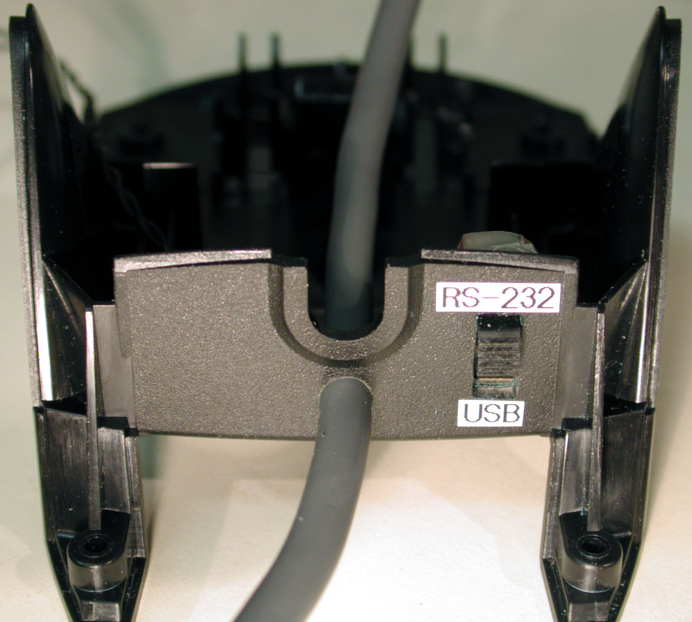
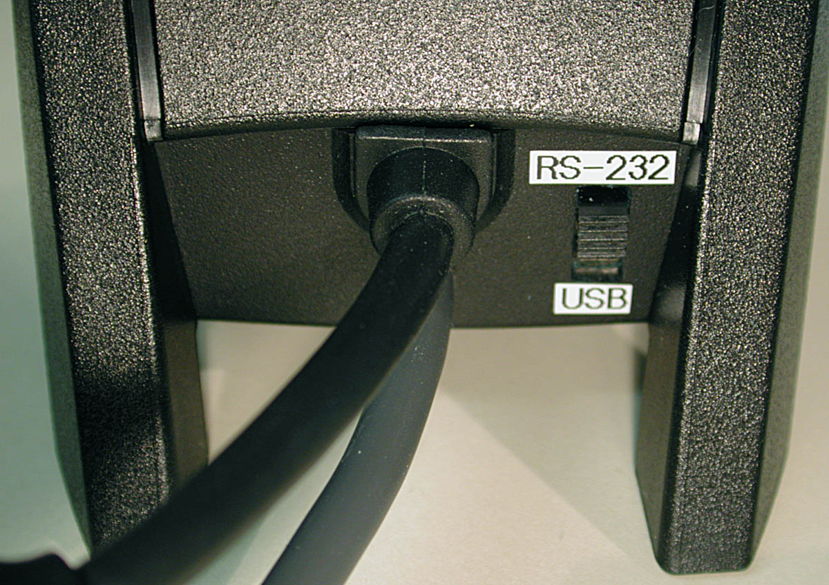
| But before you start connecting the serial cable, you should decide
whether you want a serial version only or a dual version and make the necessary
mechanical work. I did a dual version, so I made a rectangular hole for
the switch and a hole for the cable right below the standard USB cable
outlet. If you want a serial version only, just forget about all the switch
stuff. See the images below.
. |
 . . |
| .
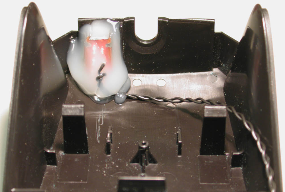
You don't have to use a slider switch which needs a rectangular hole, any simple ON/OFF switch will do it. The rectangular hole is a pain to produce, but the switch just looked nicer and I had one handy :). Easier to install are the usual 'lever-switches' which are mounted in a round central hole. Whatever you install, you have to cut off a bit of plastic of the cradle hood. It's in the way of the switch. You'll see what I mean when you try to close the cradle again. Cut it off only as far as necessary, depending on how far your switch is reaching up. The missing plastic is now problem, after all the 4 screws are shutting the cradle quite close. Solder two wires to the switch long enough to reach the PCB then install the switch. I fixed the switch just with some hot glue. Then fit the serial cable and fix it too (I used some hot glue again, I love to work with that stuff <g>). . Next you have to replace the 0 Ohm resistor right below the the connector with a 7.5 kOhm type. It's hard to describe how to desolder an SMD resistor. If you have a solder iron with a wide enough tip, try to heat up both sides of the resistor at the same time. Use a little fresh solder to maintain a good heat transfer. Don't use too much force to remove it, otherwise you have a good chance to ruin the pads on the PCB. Keep in mind what you what's important ... it's the PCB, not the resistor, we don't need it anymore! It's a bit tricky that the resistor is right between the hotsync button and the connector pads. Don't 'push' the resistor towards the connector pads once it comes loose. It not easy to get rid of shorts between pins with a pitch of 0.8mm only. . |
 |
| .
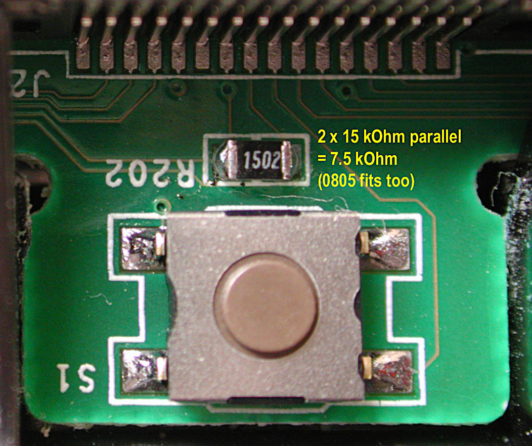
The original resistor is an 0603 size, but you can fit also an 0804. Since 7.5 kOhm are not very common (at least I didn't have one handy), I used two 15 kOhm resistors which I soldered above each other (2 times 15 kOhm in parallel equal to 7.5 kOhm). In fact you can use any resistor type as long as it fits and as long as there are 7.5 kOhm between the two pads in the end. Just don't use any old carbon resistors, the value has to be 1% accurate. . |
| Ok, now connect the serial cable and the switch (if you use one) to
the PCB according to the table. The two wires coming from the switch are
basically shorting out the resistor. Then it's 0 Ohm again which is the
USB ident. When the switch is open, the 7,5 kOhm are effective and the
Palm recognizes the serial ID. Once all the connections are made, stow
away all cables and put the PCB in place again. On the images below you
can see how it should look when everything is connected and in place.
. |
 . . |
| .
Once you double checked all connections, close the cradle again. The best way to do that is to hold the cradle top upside down so the hotsync button stays in place. Then fit the bottom from the top and close the screws again. Maybe you want to wait with the rubber feet until you gave your work a try. Not much more left to say. Just connect both cables to your PC and give it a try. Basically needless to say that switching back and forth should be done before you press the hotsync button. . A last word about my motivation: I was dying to try out WebClipping and all other online stuff with my new m505. But after buying about every modem for my previous Palms over the last few years, I found out nothing fits my new tool. I didn't even had a simple serial cable to connect to a big modem. And another overprices analog modem fitting the m505? I don't think so! On the road I use my mobile anyway, but for tests at home, the mobile connection is by far too expensive. So I decided to go with MoccaPPP from MoccaSoft which is really a great tool. But Mocca doesn't support USB (yet?), the Palm has to have a serial connection to the PC. On the other hand, I didn't want to loose the hotsync speed of USB ... now I have both. Hope you have fun too! . |
|
. Last updated: June 19th, 2001 Copyright © 1997-2001 by Peter Strobel, all rights reserved. |